How to Choose a Precision CNC Machining Supplier?
Choosing a precision CNC machining supplier is not just a search for the lowest quote. The decision affects part fit, production timing, and the cost of correcting defects. A capable supplier should understand your material, drawing requirements, and intended use—not simply confirm that a machine can cut the shape. Small details matter. A 0.02 mm tolerance, a sharp internal corner, or a specified surface finish can change the process, inspection plan, and price.
Look beyond the sales presentation. Ask how the supplier verifies dimensions, manages revisions, and handles parts that fall outside specification. Request relevant examples, inspection records, and clear answers about equipment and capacity. For a critical component, discuss measurement methods and agree on acceptance criteria before production begins. Communication matters too. A useful partner flags unclear drawings early and explains trade-offs without hiding uncertainty. That may take an extra call.
No checklist guarantees a perfect result. An impressive audit can still miss a weak handoff between engineering and production, while a smaller shop may have strong process control. Reflect on what your project truly needs: prototypes, repeat orders, traceability, or fast changes. This guide explains how to compare suppliers on technical capability, quality systems, delivery, cost, and communication. The aim is not to find a flawless company. It is to choose a dependable precision cnc machining partner whose strengths match the job—and to verify that match before committing to a full run.
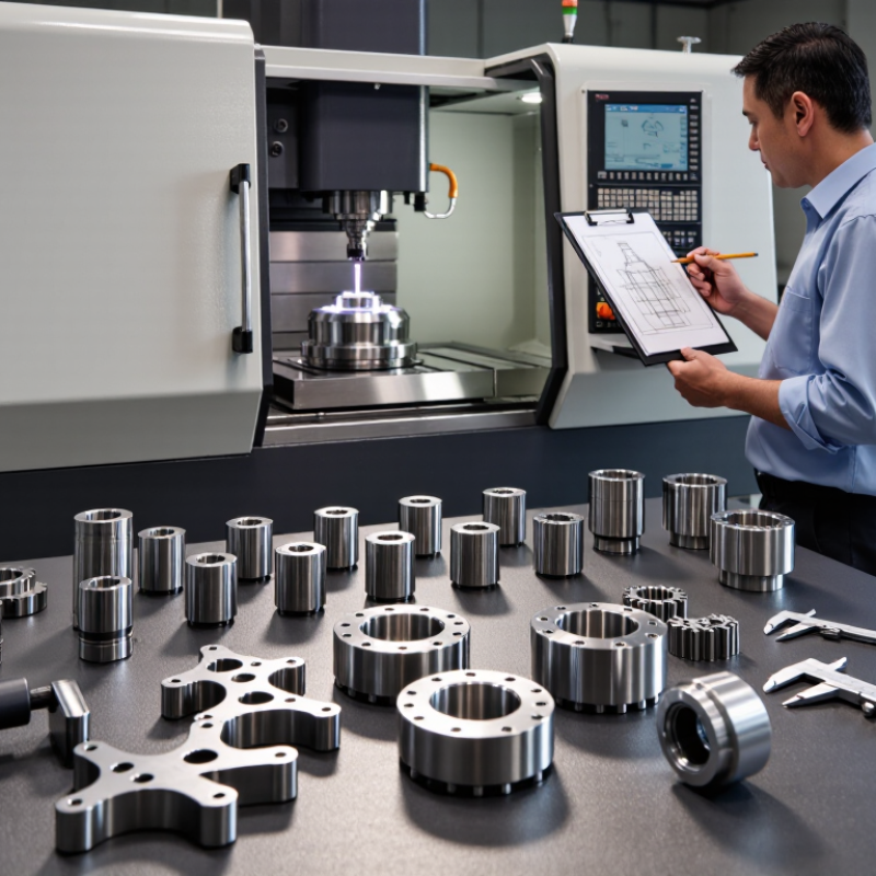
Define Part Requirements with GD&T under ASME Y14.5 and ISO 286
How to Choose a Precision CNC Machining Supplier?
Define Part Requirements with GD&T under ASME Y14.5 and ISO 286
A capable CNC supplier should understand how your drawing defines function, not just dimensions. Use GD&T under ASME Y14.5 to communicate controls such as position, flatness, and perpendicularity. Establish clear datums that reflect how the part will be assembled or inspected. A hole pattern located from the wrong datum can pass a simple size check yet fail during assembly. Small details matter.
Use ISO 286 when specifying limits and fits for mating features, such as a shaft entering a bore. State the required fit or size limits clearly, and avoid mixing conventions without an agreed interpretation. ASME Y14.5 and ISO 286 address different aspects of dimensional definition; they are not interchangeable. Ask the supplier how its inspection plan will verify critical characteristics, including the measurement method and datum setup. Even a precise drawing can leave assumptions unstated, so review those assumptions together before production.
Tips: Mark truly functional features as critical, and provide units, material, and the applicable standard edition. Request a first-article inspection report for key dimensions. Check whether the proposed measurement method can access the feature; a tight tolerance is less useful if it cannot be inspected reliably. If a requirement feels unnecessarily restrictive, revisit its function before locking the drawing.
| Requirement Area | What to Define on the Drawing | Example Requirement | What to Check with the Supplier | Acceptance Evidence |
|---|---|---|---|---|
| Drawing standard and units | Identify the applicable dimensioning and tolerancing standard, its revision, and the unit system. | ASME Y14.5-2018; dimensions in millimeters. | Confirm the supplier can interpret the stated standard and will not mix ASME and ISO conventions without agreement. | Drawing review confirms the standard, revision, units, and general tolerance notes are unambiguous. |
| Datums and setup | Choose functional datum features that establish the part’s intended locating and inspection reference frame. | Datum A: mounting face; datum B: bore axis; datum C: locating end face. | Ask how the supplier will fixture the part from the datum features and maintain that reference during machining and inspection. | Documented setup or inspection plan identifies the datum simulator or measurement method for each feature. |
| Geometric tolerances | Apply GD&T controls to functional relationships, such as position, perpendicularity, flatness, or profile. | Four-hole pattern: position tolerance ⌀0.10 relative to A, B, and C; no material-condition modifier shown. | Check that the supplier understands the tolerance zone, datum order, and any material-condition modifiers shown on the drawing. | Inspection results report the measured feature pattern relative to the specified datum reference frame. |
| Size limits and fits | State limit dimensions or an ISO 286 fit designation for mating features. Identify the nominal size and applicable fit standard. | For a nominal 20 mm hole and shaft, H7/g6 under ISO 286 gives a hole of 20.000–20.021 mm and a shaft of 19.980–19.993 mm. | Confirm the supplier can control and verify the specified size limits, and that the mating parts and fit designation are understood. | Measured hole and shaft sizes are recorded and fall within their respective limits. The stated values apply to the 18–30 mm nominal-size range. |
| General tolerances | Define general tolerances for dimensions not individually toleranced; do not use them in place of critical functional controls. | Use a clearly identified general-tolerance standard and class, or provide explicit default limits on the drawing. | Verify that the supplier’s quotation and inspection plan use the same default tolerance requirements as the drawing. | Drawing notes and inspection records show which general tolerance applies to each untoleranced dimension. |
| Material and condition | Specify material grade, product form, required condition, and any heat-treatment or stress-relief requirements. | Identify the exact material specification and condition; state heat treatment and hardness requirements if applicable. | Ask how material identity and any required post-machining treatment will be verified and traceable to the part lot. | Material certificate and, where specified, treatment or hardness records are available for the production lot. |
| Surface finish and edges | Call out surface texture on functional surfaces and define edge breaks, burr limits, or deburring requirements. | Specify the required roughness parameter and limit on the sealing face; define permitted edge break on noncritical edges. | Confirm the supplier has a suitable method to produce and measure the specified finish and to control burrs. | Surface-finish results are measured using an agreed method; visual or dimensional checks cover defined edge requirements. |
| Inspection capability | Identify critical-to-function features, inspection frequency, reporting needs, and any required measurement method. | Require recorded results for the bore size, hole-pattern position, and datum-face flatness on the first article. | Review whether the supplier’s gauges, CMM, or other measurement equipment are appropriate for the tolerances and feature geometry. | First-article inspection report includes drawing identifiers, measured values, units, and pass/fail status for designated features. |
| Production and change control | Define lot size, delivery requirements, revision control, and approval requirements for process or material changes. | Parts must be manufactured to the released drawing revision; proposed substitutions or process changes require prior approval. | Check how the supplier links parts and inspection records to drawing revision, material lot, and production batch. | Purchase and quality records identify the approved revision, lot traceability, and disposition of any nonconforming parts. |
Related Posts
-
How to Choose Precision CNC Machining Services in 2026?
-
Choosing the Right Manufacturer: A Comprehensive Comparison for the Best CNC Metal Products
-
How to Overcome Common Challenges in Sourcing the Best CNC Precision Machining Solutions
-
Discover Unmatched Quality in Best CNC Precision Machining from Leading Chinese Manufacturers
-
Understanding Common Issues in Precision CNC Machining Processes
-

Unlocking Precision: The Advantages of CNC Metal Machining in Modern Manufacturing
Let's Build Together

Contact Us: Call 435-563-3503
-OR- Fill in the form below and we will call you back.