How Does a CNC Machine Work in 2026?
In 2026, a CNC machine turns digital instructions into controlled movement. A machinist creates or imports a part design, prepares toolpaths, and sends verified code to the machine’s controller. The controller coordinates axes, spindle speed, and cutting motion. That is the core of cnc machine working.
Consider a small aluminum bracket. A fixture holds the stock firmly while a cutting tool follows programmed paths across its surface. Motors move the table or spindle along precise axes. Sensors and control systems help maintain position, but they do not make setup errors disappear. A dull tool, loose workholding, or incorrect offset can still ruin a part. Details matter.
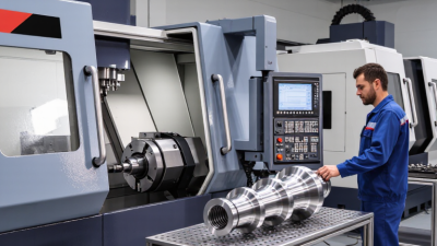
Modern equipment may include automatic tool changers, probing systems, and software that helps detect process problems. Yet the exact workflow depends on the machine, material, tooling, and operator. A mill removes material with a rotating cutter; a lathe usually rotates the workpiece against a cutting tool. These differences shape how programs are prepared and checked.
The diagrams often look simpler than the real process. That deserves a second look. This guide explains how design data becomes machine motion, what each major component does, and where human judgment remains essential. It also covers setup, machining, inspection, and common sources of error, so readers can understand not just what a CNC machine does, but how reliable results are achieved.
What a CNC Machine Is and How Its Main Components Work
A CNC (computer numerical control) machine follows programmed instructions to move a cutting tool or workpiece along controlled paths. Its controller interprets the program and coordinates axis movement, spindle speed, and other settings. Depending on its design, the machine may mill, turn, drill, or perform another operation. Not magic.
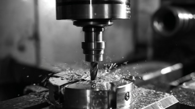
The controller acts like the machine’s coordinator. Motors and drives move the axes, while guideways and screws help keep that movement steady. A spindle holds and rotates the cutting tool on a mill; on a lathe, it usually rotates the workpiece. Workholding keeps the material secure. Feedback devices, such as encoders, report position so the control system can detect movement accurately. Details vary by machine.
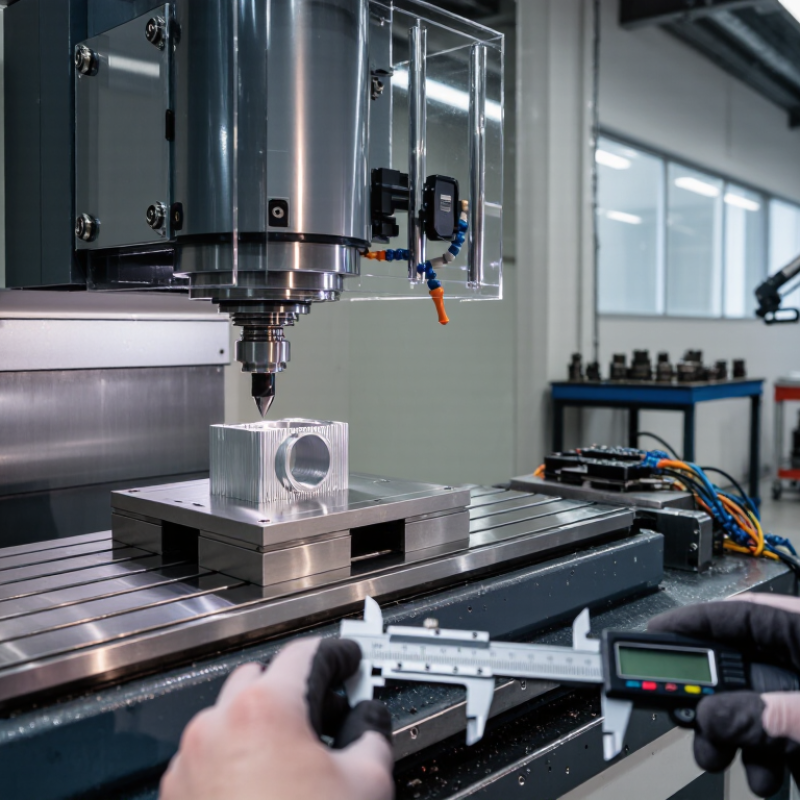
The operator sets tool and workpiece offsets before cutting. For example, a block of aluminum may sit in a vise while the tool follows a path through its surface. A test run can reveal a misplaced offset before the cutter touches the material. In practice, setups are less tidy than diagrams suggest: a tool may wear, a chip may cling to a fixture, or a measurement may be slightly off. Coolant and guarding help manage heat and chips, but they do not replace careful setup and inspection.
How a Digital Design Becomes CNC Instructions
How Does a CNC Machine Work in 2026?
A digital design becomes CNC instructions through several careful translations. An engineer creates a 3D model, then CAM software assigns operations such as facing, drilling, and contouring. The programmer selects a cutter, sets cutting speeds, and defines how the tool approaches the material. A 6 mm end mill might trace a pocket in several shallow passes rather than cut its full depth at once.
CAM software calculates toolpaths, but the machine needs instructions its controller understands. A postprocessor converts those paths into machine-specific code, often including coordinates, spindle commands, and tool changes. Before cutting, the programmer checks the setup, work offsets, and tool lengths. Simulation can reveal collisions, but it cannot prove every real-world condition. The stock may be clamped slightly differently. Small changes matter.
This digital thread matters as factories connect design and production. Deloitte’s 2024 Smart Manufacturing Survey found that 86% of manufacturing executives expected smart manufacturing to be a primary driver of competitiveness within five years. The same survey reported that 83% believed it could transform production. Those figures describe executive expectations, not guaranteed results. A sensible workflow still depends on verified tools, correct material data, and a careful first run. The screen can look perfect; the first cut may disagree.
How the Machine Prepares and Secures the Workpiece
Before a CNC machine cuts, the workpiece must be clean, located, and held firmly. Chips or dried coolant beneath the stock can tilt it by a fraction of a millimeter. That small error may affect every feature. The operator checks the material against the job drawing, then identifies a reference face or edge. This datum gives the machine a reliable starting point for its coordinates.
The workpiece is placed in a vise, fixture, or other suitable holding device. Clamps should resist cutting forces without bending thin material. Their positions also need to clear the tool’s path. Small details matter. A setup can look square and still be slightly out of alignment, so appearance alone is not enough. The operator may use an indicator or probe to check position and surface height, then enter or verify the work offset in the control.
The stock should extend far enough from the fixture for the cutter to reach the required surfaces, but not so far that it vibrates under load. This balance is easy to underestimate. A short test move, with the spindle stopped, can reveal a clamp or toolholder collision before cutting begins. The machine may also probe the workpiece to confirm its location. If the measured position differs from the expected one, the setup needs attention before the cycle starts.
How Does a CNC Machine Work in 2026? – How the Machine Prepares and Secures the Workpiece
| Preparation Stage | What Happens | Typical Method or Guidance | How It Is Checked |
|---|---|---|---|
| Review the part and stock | The operator confirms the material, stock dimensions, finished-part requirements, and machining allowances before loading. | Compare the stock with the job setup sheet and drawing. Leave enough material for the planned facing and finishing operations. | Check material identification and measure the blank with suitable tools such as calipers or a micrometer. |
| Clean contact surfaces | Chips, burrs, coolant, and dirt are removed from the workpiece and the surfaces that support or locate it. | Wipe the vise jaws, fixture, parallels, and workpiece seating areas. Remove burrs without changing critical dimensions. | Inspect the contact areas visually and confirm the workpiece sits flat without rocking. |
| Choose the workholding method | The workholding is selected to resist cutting forces while allowing tool access and avoiding distortion. | Common options include a vise, clamps, a chuck, collet, fixture plate, or vacuum fixture. The choice depends on part shape, material, and operation. | Confirm the setup supports the part adequately and does not obstruct the toolpath or machine movement. |
| Locate and support the part | Locators, stops, parallels, or fixture features position the workpiece consistently and support it during cutting. | Seat the part against the intended locating surfaces. Use supports where needed, especially for thin or flexible workpieces. | Check that the part is fully seated and that supports do not lift or twist it. |
| Clamp securely | Clamping force holds the workpiece in place without crushing, bending, or shifting it. | Apply appropriate, even clamping force. Use soft jaws or protective pads when the surface or geometry requires them. | Check for movement by hand only when the machine is stopped and safe to access; recheck clamp engagement before machining. |
| Establish the work coordinate | The machine’s program reference is aligned with a defined point on the secured workpiece. | Set the work offset using the specified datum and an appropriate probe, edge finder, or measurement method. | Verify the measured datum and offset against the setup instructions before running the program. |
| Check clearance and tool access | The operator confirms that tools, holders, clamps, and machine components can move through the planned operations safely. | Review the programmed path and setup; ensure clamps and supports are outside the cutting path and that adequate clearance remains. | Use the machine’s approved simulation, graphics, or dry-run procedure where available. |
| Perform a final setup check | The complete setup is checked before cutting begins. | Confirm the workpiece is secure, the correct program and tools are selected, and guarding and coolant arrangements are ready. | Follow the machine and workplace safety procedures. Keep doors or guards closed during operation as required. |
Workholding choices, clamping force, and setup tolerances vary with the machine, material, part geometry, and cutting operation. Follow the machine manual and approved shop procedures.
How CNC Operations Shape the Workpiece Step by Step
A CNC machine shapes a workpiece by following programmed movements, but the result depends on careful setup. The operator secures the raw material in a vise, chuck, or fixture. A loose workpiece can shift under cutting forces. That small movement may spoil a dimension.
The machine needs a reference point. The operator sets the work offset and checks the tool length, so the programmed coordinates match the actual setup. CAM software converts a digital design into toolpaths and cutting instructions. The controller then moves the tool and workpiece along selected axes.
In milling, a rotating cutter removes material; in turning, the workpiece spins against a cutting tool. Small details matter. The first pass may remove bulk material, while later passes leave a smoother surface and bring features closer to their target dimensions.
During cutting, coolant may reduce heat and help clear chips, depending on the material and operation. The operator watches for unusual vibration, chip buildup, or a changing sound. The sequence is orderly on screen, but setup is where reality gets less neat. A tool can wear, and a fixture can flex slightly.
After machining, measurements with calipers, micrometers, or gauges show whether the part meets its specified dimensions. Some surfaces still need another pass.
How Sensors, Operators, and Safety Systems Monitor the Process
In a CNC machine, the cutting path may be programmed, but the live process still needs watching. Sensors track spindle load, vibration, axis position, coolant flow, and enclosure-door status. Their readings can reveal a dull tool, a loose fixture, or a cut beginning to chatter. Small changes matter.
An operator checks these signals against the sound and appearance of the cut. A sudden rise in spindle load may call for a feed-rate adjustment or a tool inspection. The screen helps, but it does not explain every cause. A vibration alert might point to poor tool setup, not a failing motor. That distinction takes experience. And judgment.
Safety systems monitor conditions that should stop or limit machine movement. Door interlocks prevent cutting from continuing when an access panel is open, while emergency stops let staff halt motion quickly. These safeguards reduce exposure to moving parts and flying chips; they do not replace safe procedures or attentive supervision. Sensors also need maintenance and calibration. A dusty window, damaged cable, or misaligned probe can produce misleading readings. On the shop floor, someone still needs to question an unusual number before trusting it.
Related Posts
-
Top 10 Precision CNC Machining Suppliers in China?
-
Unveiling the Comprehensive Technical Specifications of the Best Large CNC Machine
-
Why You Should Invest in a Home CNC Machine for Your DIY Projects
-
How to Choose the Right Machining Parts for Your Project Needs
-
10 Best CNC Metal Parts Manufacturers for Global Buyers
-

The Best 10 CNC Precision Machining Techniques You Should Know?
Let's Build Together

Contact Us: Call 435-563-3503
-OR- Fill in the form below and we will call you back.